On February 22, 2018, CSE Magazine hosted a webinar called "Critical Power: Motors, Variable Frequency Drives (VFDs), and Variable Speed Drives". Some of the attendees brought up some good questions relating to specifying shaft grounding rings and bearing damage that we'd like to address here:
1. Can VFDs damage motors? If so, how?
Yes, the pulsed nature of VFD output voltage can damage motors in multiple ways. Firstly, high peak voltages and fast rise times can burn out the insulation in non-inverter duty motors. Inverter duty motors mitigate this damage by using Class F or H insulation in their motor windings.
But VFDs also damage motor bearings (by mechanisms described below), and most so-called inverter duty motors do not yet include protection against VFD-caused electrical bearing damage. To avoid premature bearing failure, it would be prudent for a specifying engineer to require that VFD-fed motors be equipped with factory-installed shaft grounding rings.
Specifying suitable motors is the key, and all of the following motor manufacturers have motors with shaft grounding rings factory-installed:
- Baldor
- WEG Electric
- Regal Beloit (Marathon, LEESON)
- TECO Westinghouse
- GE
An actual example of a specification follows:
SECTION 23 05 13 – ELECTRICAL PROVISIONS FOR HVAC EQUIPMENT
1.3 B. Electrical bearing damage protection: Submit product data and installation instructions for each of the following conditions:
1. New fan and motors.
2. Retrofitted fan and pump motors.
3. Shaft voltage tester.
2.1 MOTORS
Inverter Duty Motors: Where fan or pump motors are used in conjunction with, or controlled by, a variable frequency drive (VFD), motors shall be premium efficiency, suitable for VFD operation, in accordance with NEMA MG.1 (This paragraph could also include the phrase "...with Inverter rated winding insulation and shaft grounding rings installed by the motor manufacturer)
2.2 ELECTRICAL BEARING DAMAGE PROTECTION
A. Shaft Grounding Rings
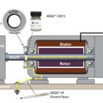
- All motors operated on variable frequency drives shall be equipped with a maintenance free, conductive microfiber, shaft grounding ring with a minimum of two (2) rows of circumferential microfibers to discharge electrical shaft currents within the motor and/or its bearings.
- Motors up to 100 HP shall be provided with a minimum of one (1) shaft grounding ring installed either on the drive end or non-drive end.
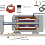
- Motors over 100 HP shall be provided with an insulated bearing on the non-drive end and a shaft grounding ring on the drive end of the motor.
- Grounding rings shall be installed in accordance with the manufacturer’s recommendations.
- Existing Motor Retrofit:
- Grounding Ring Kits shall be equivalent to Aegis SGR uKIT, solid ring only. Grounding Rings shall be suitable for Drill and Tap installation or Conductive Epoxy installation.
- Drill and Tap: Avoid using Loctite or other non-conductive material to secure the screws.
- Conductive Epoxy: Remove paint from motor surface, apply epoxy and hold bracket in place until firm. Allow epoxy to cure for 4 hours at 75F, or use a heat gun continually for 10 minutes, then allow to cool.
- Colloidal Silver Shaft Coating: The silver coating enhances the conductivity of the shaft and also lessens the amount of corrosion that can impede the grounding path. Apply to the shaft where the grounding ring microfibers are to be installed. Use a heat gun to cure. Apply a second coat, and re-cure.
B. High-Frequency Ground Strap
- Provide grounding straps as manufactured by AEGIS, or equivalent to ensure a very low impendence path to ground from the frame of the motor for high frequency currents generated by VFDs.
- Grounding straps shall be constructed of flat braided tinned copper with tinned hole at one end and ring terminal at the other. All motors operated on variable frequency drives shall be bonded from the motor foot to system ground with a high frequency ground strap made of flat braided, tinned copper with termination to accommodate motor foot and system ground connection.
- Continuity Testing: After installation, test for conductive path to ground using Ohm meter. One probe on metal frame of SGR and one probe on bare metal of motor frame. NOTE: motor must be grounded to common earth ground according to applicable standards.
C. Shaft Voltage Testing
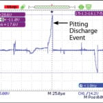
- Measuring the shaft voltage on VFD driven motors provides the valuable information to determine if there is a potential risk of bearing damage from electrical bearing discharges.
- Shaft voltage readings and waveforms shall be used to validate motor performance.
- Provide shaft voltage testing kit equivalent to Aegis Model OSC-9100MB-W2, complete with the following:
- Two 1x / 10x probes, one shaft voltage probe with SVP tip
- 1000V CAT III multimeter test leads
- Instant image capture feature
- USB flash drive for waveform recording
- 5-hour rechargeable Lithium Ion battery
- Carrying case.
PART 3 - EXECUTION
3.2 BEARING PROTECTION TESTING
- Bearing protection shall be tested for each VFD driven motor, in accordance with manufacturer’s recommendations.
- Shaft voltage testing shall be performed by a factory-trained and authorized Aegis technician. Technician shall train the owner’s personnel and demonstrate the proper use of the testing equipment.
- Record test results and incorporate into project closeout documentation.

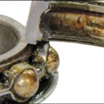
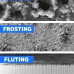
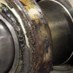
2. What about common mode ground current, bearing fluting?
There is more than one source of bearing currents in VFD-fed motors, any one of which can lead to fearing fluting damage and failure. There are many technical papers published on this subject, for example "A Practical Guide to Understanding Bearing Damage Related To PWM Drives" by Don MacDonald and Will Gray, and ABB Drives' Technical guide No. 5: Bearing currents in modern AC drive systems
The two most common sources of bearing currents are capacitively induced EDM Currents and high frequency circulating currents, which are addressed in detail in the AEGIS Bearing Protection Handbook.
- Capacitively induced currents are from the common mode voltage
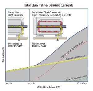 supplied from the drive to the motor - positive and negative pulses - which are then capacitively coupled/electrostatically induced onto the motor's shaft, and which then may discharge in the motor's bearings. These capacitive EDM currents are present in ALL VFD driven motors and require a path to ground away from the motor's bearings - such as is provided by the shaft grounding rings described in question 1 above.
 - High frequency circulating currents are present in motors over 100 HP (75 kW) and result from electromagnetic induction. They are induced along the shaft by the magnetic field from the common mode current in the stator windings. These currents circulate from frame to shaft and back, through the motor bearings.
3. What is AEGIS' role in motors & drives?
AEGIS shaft grounding rings are specifically designed to provide the most reliable path to ground for capacitive induced bearing currents. The AEGIS ring’s unique design features hundreds of thousands to millions of specially engineered conductive microfibers that encircle the motor shaft. With so many electrical transfer points the ring provides continuous electrical contact.
Designed with specific mechanical and electrical characteristics that minimize wear and maintain conductivity, AEGIS microfibers will last for at least the L10 life of the bearing. Based on wear of less than 0.001” [0.025mm] during 10,000 hours of testing, they are expected to withstand over 200,000 hours of continuous operation.
Through our patented design, AEGIS conductive microfibers are a wear-to-fit design which ensures that the fibers don’t “wear out” during the bearing’s life They exhibit minimal wear with the ability to flex without breaking. During the life of the ring the minimal wear characteristics ensure that the fibers only wear to the exact diameter of the motor’s shaft and no further, maintaining the nanogap contact which allows the AEGIS ring to continue to operate effectively and protect the motor’s bearings. In testing, the fibers were proven to withstand 2 million direction reversals (to 1800 RPM) with no fiber fatigue or breakage.
However, shaft grounding rings cannot prevent damage from high frequency circulating currents in larger motors. In motors over 100 HP (75 kW), one bearing must be insulated, with a shaft grounding ring at the other end. Insulating just one bearing interrupts circulating currents and prevents their flow, while the AEGIS ring discharges capacitive shaft voltage (which is still present in larger motors).
4. What about shaft grounding rings for motors in classified areas, and UL listing for motors in non-classified areas
- Hazardous areas: External shaft grounding is not allowed for hazardous environments (Class 1 Division 1, Division 2 or Class 1 Zone 1, Zone 2). However, AEGIS shaft grounding rings may be installed inside an Explosion Proof enclosure per IEEE Std 303™-2004 or inside an XP motor. Marathon Motors manufactures XP motors with AEGIS factory-installed.
- CE and UL requirements: AEGIS® Rings are classified as a “component” and as such are not subject to the requirements of any Directive. The application of CE or UL Mark is not applicable to this component.
5. dV/dt and the need for load reactors with inverter-duty VFDs
Variable frequency drives' output comprises a series of voltage pulses with extremely rapid off-on transitions. dV/dt is just the rate of change in voltage at during a transition, and is the change in voltage divided by the rise time of the pulse. Typical values are dV = 460 volts and a 20 ns rise time, giving dV/dt = 23,000 volts per microsecond! These transitions are also often measured by their frequency, defined as the reciprocal of the rise time. 20 ns corresponds to a 50 MHz frequency.
With that background, the question of when to use a dV/dt filter must be evaluated. Generally, if there is an impedance mismatch between the VFD and the motor, reflected waves can "amplify" the dv/dt transition which could result in a "overshoot" of voltage which may be 2 or more times higher than the supply voltage. This means that there may be a transition that spikes up to 1000 volts or more on the leading or trailing edge of the pulse. Even inverter-duty winding insulation may break down under voltage spikes like this. In these cases adding a dV/dt filter will help to filter this voltage spike.
 H
H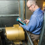 owever, it should be noted that in the motor's stator windings the pulses will still cause capacitively induced shaft voltage and therefore even with the dV/dt filter bearing discharges would still take place so shaft grounding rings are still needed to provide a path to ground for shaft voltages.
One can measure the shaft voltage with an oscilloscope such as the AEGIS Shaft Voltage tester which would display the presence of shaft voltage and bearing discharges should no shaft grounding ring be installed on the motor.