

The article below corrects and adds to the EASA Current's article from the Dec 2017 issue: “Motor bearings: Electrical damage simplified.”
An article on electrical bearing damage recently appeared in EASA Currents Magazine. While it raised a lot of good points, it also contained information on shaft grounding practices and shaft grounding rings which need correction or further examination. As we discuss electrical bearing damage, please note that we are referring to motors operated by variable frequency drives (VFD).
The title of the article was “Motor bearings: Electrical damage simplified.” True to this title, the article tries to stay as “nontechnical” as possible. Unfortunately, staying “nontechnical” is not always desirable since a thorough understanding of bearing currents and solutions is critical for successful repairs. As the inventors of conductive microfiber shaft grounding rings – the AEGIS® products - we’ve been discussing electrical bearing damage and its solution for over twelve years. It is my opinion that in trying to keep it simple, the article sometimes oversimplifies the problem.
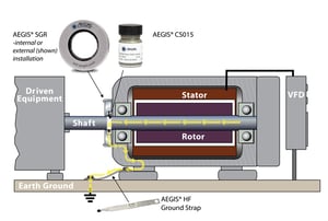
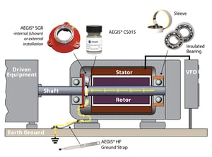
When talking about shaft grounding, it is a mistake not to differentiate capacitive shaft voltage discharge currents (EDM currents) and circulating currents (be they low or high frequency). The author states that his preferred method of bearing protection is to “break the electrical circuit on the opposite drive end (ODE)” of the motor, and install shaft grounding at the drive side. 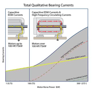 This mirrors our recommended approach for AC motors over 100 HP and for all medium voltage motors. However, circulating currents are not an issue in small AC motors (under 100 HP), so bearing insulation is unnecessary for them and adding a shaft grounding ring to the DE or NDE is sufficient to protect the motor’s bearings.
But the author then states that “if the [shaft] voltage can be clamped low enough with just a grounding brush, the ODE insulation is not always necessary.” This is false. Shaft grounding cannot prevent circulating currents. So, 100 HP+ and medium voltage motors would still be at risk of circulating currents. These motors will always need both shaft grounding (preferably the drive end), and some type of insulation at the opposite end (preferably the ODE).
There is another confusing or confused statement about circulating currents in the same paragraph: “This looping is also the reason [not to] install shaft grounding on the ODE as the loop can extend into the driven machine” and thereby damage its bearings. This is easily misconstrued to mean that shaft grounding should never be installed at the ODE. But it is important to know that this applies only when circulating currents are a potential problem, i.e. motor over 100 HP and medium voltage motors.
When discussing circulating currents potentially extending “into the driven machine” we advise referring to the IEEE 112 which recommends insulating the NDE to avoid a circulating current path in the driven machine. Last but certainly not least, it is important to remember that installing a shaft grounding ring on the DE is still necessary to prevent capacitive voltages from causing EDM damage to the steel (non-insulated) bearing and/or going down the shaft to the driven equipment.
Now for a discussion on shaft voltages: The author gives a maximum safe shaft voltage level of 5 V peak to peak, and correctly points out that there is no universally applicable “safe” level of shaft voltage. In fact, it the peak voltages which harm the bearings so discussing “peak” voltage is key. The NEMA MG1 document gives a range of 10 to 40 volts peak (20 to 80 volts peak to peak) as the shaft voltage level where bearing discharge can occur. But every system is different; every motor in every state of operation will have its own bearing breakdown voltage where discharge through the bearing occurs. With the lack of a consistent safe level across systems, neither peak voltage nor peak-to-peak measurements are a reliable measure of risk.
Therefore, we recommend that machine owners or motor repair technicians take shaft voltage readings with a high-speed oscilloscope (at least 100 MHz bandwidth). With this equipment, you can unambiguously tell whether discharge is occurring in the bearings. The smoking gun is a discharge pattern in the shaft voltage waveform (a slow voltage buildup followed by a rapid transition down).
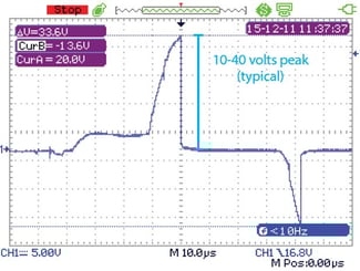
While the article recommends shaft voltage testing, it only recommends measuring peak-to-peak voltage, even though it is not the most important measure. The sample shaft voltage reading in the article has a timescale of 2 ms/div, which is far too long to detect discharges, which occur on a timescale of microseconds. More on this in the Bearing Protection Handbook.
The shaft grounding ring section starts off well, but goes awry in the second sentence by referring to “the standard single row ring.” This refers to the AEGIS® SGR, for low voltage motors, but SGRs have two rows of conductive microfibers, not one. Next the article states that the standard SGRs are “usually” sufficient for smaller motors, but “may not always provide a low enough resistance circuit [sic] to ground.” An SGR with two fiber rows is extremely effective and is proven in millions of applications worldwide on low voltage motors under 500 HP (and as noted earlier, motors over 100 HP also need bearing insulation in addition to the SGR ring).
The article does better when talking about the six fiber-row AEGIS® PRO Rings, saying “These rings are the best option for the least amount of maintenance.” AEGIS® PRO rings are in fact the best and recommended option for medium voltage motors and LV motors over 500 HP.
The author does seem confused, though, about the purpose of the extra rows of conductive microfibers in the PRO ring. He seems to think the extra rows are to decrease the PRO’s resistance relative to an SGR. But in fact, the extra rows serve to increase current carrying capacity, not resistance/impedance per se. This extra capacity is needed for medium voltage and large low voltage motors (500 HP+) because they have higher shaft currents and the PRO ring’s extra rows accommodate that increased current.
The article later claims that “they can be susceptible to wear, heat, and grease contamination.” It is unclear whether “they” refers to PRO rings or SGRs, but the claim is inaccurate for either product. Any properly installed AEGIS® ring is not susceptible to wear. It is designed as a “wear-to-fit” device; the fibers slowly wear until they just-touch the shaft surface, a process which can take 200,000 hours or more. Electrical contact is maintained, by physical contact and near-contact electron transfer, so the ring does not stop working. As for heat tolerance, the manufacturer spec states that AEGIS® rings can withstand temperatures up to 410° F (210° C), and we know of at least one customer who uses AEGIS® rings in an oven at 400 degrees.
As for grease, the AEGIS® fibers cut through and tolerate light grease, but this is a moot point. As the article mentions, AEGIS® rings can be mounted inside motors, away from external grease and grime, and this is where motor repair shops should install them. One bit of information the article left out is that there is even a UL-approved process for installing AEGIS® rings inside explosion proof motors, which is unique among shaft grounding technologies.
Now we come to the author’s preferred shaft grounding method, the copper bristle brush. These devices have a few shortcomings that went unmentioned. The brush’s springs may clog and jam, copper is easily oxidized to its nonconductive green/blue oxide, and the shaft can glaze. Also, we are rather skeptical about the use of grease on the brush.
The article only mentions common mode chokes (CMC) briefly, but manages to get a few errors into those three sentences. The most important one to correct is the misleading statement that they “do not always reduce the shaft voltage to a low enough level to eliminate bearing damage.” In fact, common mode chokes barely affect shaft voltage at all and do nothing to eliminate EDM bearing discharges from the capacitive induced shaft voltage. CMCs are just not useful against the shaft voltage discharge currents that shaft grounding protects against. They may be able to reduce high-frequency circulating currents, but CMCs are not as effective as insulating one bearing, as described above. At any rate, common mode chokes cannot take the place of shaft grounding.
All that said, the article ends with some good preventive maintenance advice, including making regular shaft voltage measurements, and advising specifying engineers to call for motors with preventive measures installed. It ends, “Good service centers will identify electrically damaged bearings and strive to recommend the best method to prevent further issues.” We agree wholeheartedly. Bearing inspection is required by the ANSI/EASA Standard AR100-2015, and by the EASA warranty checklist, and is also one of the processes required of accredited EASA motor repair shops.
Ultimately, this article was written to educate motor repair shops and more importantly, to help them improve their processes and so improve their business. We agree with these goals and hope that the original article succeeds in encouraging an enlightened discussion and seeking the most accurate information when considering bearing protection. And we hope that this article, too, will help advance those goals.